Perkins 4-108 Low Line
FRESH WATER COOLING SYSTEM--notes
Heat Exchanger Perkins P/N NA001406
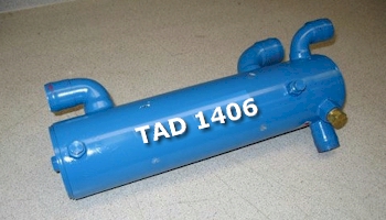
$400 from TAD
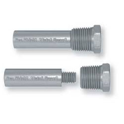
Pencil zinc anode for Heat Exchanger: E-1 Anode Pencil 1/2 x 2" 11/16" head--1/2" needs to cut off the anode prior to installation in the heat exchanger
NOTE: I purchased a new (used)
coolant reservoir in 2009 (it's in the dock box), so if (more likely when) the original
one finally breaks there is a replacement available for it.
RAW WATER SYSTEM
SHERWOOD G65 RAW WATER PUMP
-
(replaced March 2009)
- (rebuilt [British Marine] April 2014)
RAW WATER PUMP
IMPELLER BLADE DEFLECTION
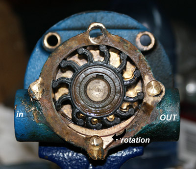
Note that the pump is
installed "upside down" and the INTAKE is on the
STARBOARD SIDE of the pump. Rotation is as noted (clockwise if
upsidedown, counterclockwise if right side up... :<).
March 2009: The
pump pictured was installed in 2001. I had to drill the screws
out of the cover to open the pump (cobalt drill bit $12), but
the impeller was just fine. (Yes, I tried the "propane
torch" method to loosen the screws, but to no avail.)
Compared to its replacement unit, however, this pump is very
hard to rotate so I think the bearings must be worn.
CLOSE THE ENGINE WATER COOLING
SEACOCK
IMPELLER REMOVAL: DO NOT USE A SCREWDRIVER, PLIERS, OR ANY OTHER TOOL
THAT MIGHT DAMAGE THE INTERIOR PUMP BODY.
Lever between the
blades from the sides using the Quick Impeller Remover (red
plastic thing) provided with the SpeedSeal kit or an impeller puller. If you can't get
the impeller out, call a mechanic who has a small impeller puller or remove the pump and take
it to a machine shop. The bottom TWO studs come out with the nuts, so be careful.
If you are replacing the pump, make sure that the SPLINE lines up with the groove
on the pump.
Flexible Impeller: 1-1/4" Wide x 2-7/16" Diameter. Sherwood 9959K minor repair kit.
REPLACING THE IMPELLER: use a plastic
wire tie to compress the blades with blades deflected
correctly. Grease impeller with LITHIUM GREASE and push into the pump cavity
making sure to line up the spline with the "key" on
the shaft.
REPLACEMENT OF THE "O" RING:
lightly grease the groove in the SpeedSeal cover and install a
new "o" ring.
The OUTLET pipe (port side of the pump) has two hoses--one is CURVED and that side
attaches to the pump itself. The other side has a straight hose and that attaches to the heat exchanger.
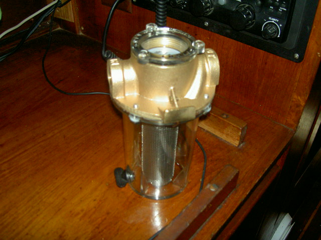
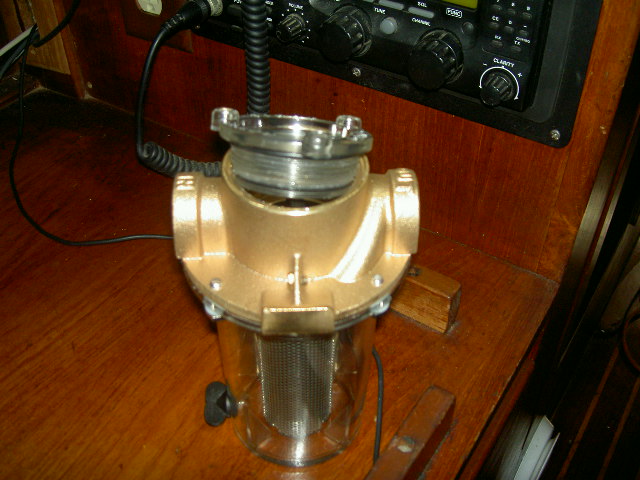
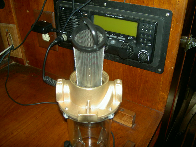
RAW WATER SYSTEM--GROCO ARG-750 RAW WATER STRAINER
FUEL SYSTEM
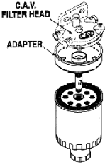
 INSTALLATION & REMOVAL OF NAPA 3361 SECONDARY FUEL FILTER:
- REMOVAL: unscrew it CLOCKWISE from the CAV HEAD.
- INSTALLATION: screw the filter on COUNTER CLOCKWISE to orientation of the CAV HEAD
- VIDEO HELP
 =======>>>>>
BLEEDING THE FUEL
SYSTEM (written in clear English)
Word Document
Turn on the IGNITION SWITCH. Engage the
electric fuel pump.
Using a 5/8" wrench, loosen the bolt
on the top of the SECONDARY filter (the one attached to the engine block). Operate the
lift pump until fuel, free of bubbles, eminates from there.
Tighten that bolt. Then, using a 5/16" wrench, loosen the
SIDE BLEED VALVE on the fuel injection pump (only the
side one--even though the book says to bleed the top
one LEAVE THAT ONE ALONE!); use a 1/2" wrench to loosen the
SUPPLY LINE (rear) to the injection pump. Operate the lift
pump until fuel, free of bubbles, eminates from both of those.
Tighten both.
OPTIONALLY: Ensure the STOP CABLE is in the RUN POSITION.
Position throttle at FULL then loosen #1 and #3 injector lines
at the injectors and crank the engine (about 10
seconds--then wait 1 minute) and repeat until fuel flows from
those lines. Tighten the injection lines to the injectors.
MAKE SURE BOTH THE STARTING BATTERY AND THE IGNITION ARE ON!!! AND then move throttle to just above idle, and start the
engine.
NOTE: MOST TIMES, if you get clear fuel from the side bleed valve on the injection pump, the engine will start after the third or fourth try (a trick I learned from the injection pump rebuild shop...).
Note about lift
pump: the supply line to the lift pump has a check
valve in it. So if you take that off, make sure you get
it back on the same way it came off or you will NOT GET FUEL
OUT OF THE LIFT PUMP (ask me how I know).
JANUARY-JUNE 2008:
Had the injection pump rebuilt by a local shop at a cost of
$1300. Took six weeks (apparently they had to order a part
from England and it was delivered by row boat). When
installed, no fuel came out of the pump. After THREE MONTHS of
f@#ing around with it, an email from Dave Lively in Louisana
suggested that perhaps the shop REVERSED THE STOP AND RUN
POSITION of the fuel shutoff--he was right.
Just for S's and G's, we replaced the lift pump and rest
of the fuel delivery system as well.
NOVEMBER 2007: As a result of
the (2007) top-end rebuild and the refresh of the engine
cooling system (cost $1564.00), engine operating temperature
has dropped from 190°F to 180°F under load at about
1800rpm.
Instrument Cluster
Remember that the
tach works off of the ALTERNATOR, so in order to get an idea of RPMs, the REGULATOR DISCONNECT switch must be switched on.
The "AMP" meter has never worked, and the knot meter mounted on the port cockpit wall stopped working after 5500 miles (but it outlasted the Raymarine knot meter by 2000 miles).
The IGNITION switch must be energized for the instrument lights to work.
PSS Shaft Seal
-
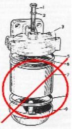
When a boat with a
watertight (P.S.S.) seal goes back in the water, there will be
an air pocket trapped in the shaft log (stern tube). This air
pocket must be vented so water can reach the face of the seal
to help cool and lubricate it. To vent the air pocket, simply
compress the bellow (push the carbon away from the stainless
steel rotor with your hand) so that water fills the shaft log
(stern tube). A small amount of water will enter the boat at
this time and will stop as soon as you release the bellow,
allowing the two faces to come back in contact. In the graphic
below, one would move the bellow from the #5 in the direction
of the #2.

Water will seep into the boat. When you see the water,
the air pocket is vented.
January 2008: after sitting for about 4 weeks,
the graphite flange somehow became attached to the stainless
steel rotor, the result being near disastrous. When the engine
was started and reverse was engaged, the bellow twisted itself
out of the clamps and ended up folded in half. Water was then
entering through the stern tube as there was no seal. Further
investigation revealed that the boat yard that installed the
seal had replaced a nylon fitting with one made of stainless
steel (the manufacturer specifically warns against such
replacement), and a resulting corrosion caused the two
surfaces to bond. Faced with the probability that the boat
would have to be towed to a boatyard to be hauled, I
reluctantly sprayed Corrosion-X on the rotor and flange. Three
days later, the corrosion bond broke and the bellow retracts
again. Unfortunately, the Corrosion-X will decay the rubber
parts of the seal, so the seal will have to be replaced. For
reference: shaft size is 1”, stern tube is 2x2”.
The cutless bearing was replaced in December 2012.
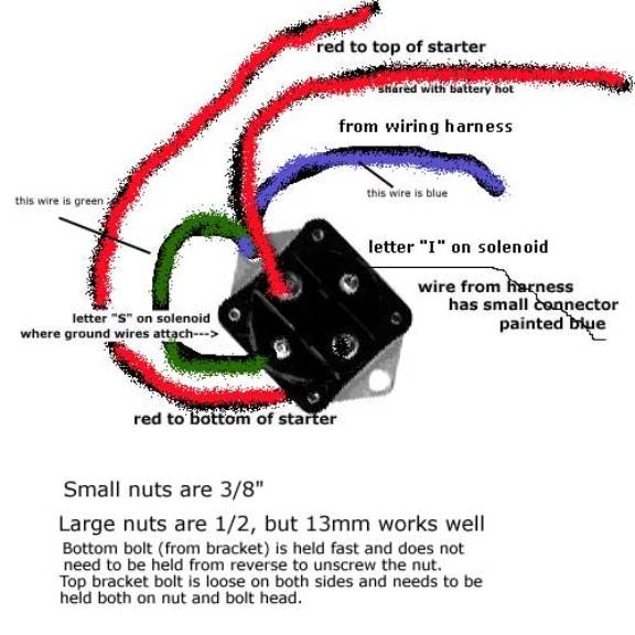
Starting the engine
Possible reasonss for the
engine failing to start*:
- Remove start switch relay
failure or wires disconnected/loose/corroded connections (it's pretty particular about how tight the wires are)
- Bad (remote) starting switch or wiring
thereto
- Flat starting battery
- Starter (or starter solenoid) failure
- Insufficient fuel supply
- Air in the fuel line(s)
* out of 997 attempts over 12 years, the engine failed to start only one time--probably due to air in the secondary fuel filter (corrected with the installation of the DP-1000 adapter) breaking the bleed.
 To
remove the range top, first remove the machine screws that
hold the DRIP PANS. Then, find the small levers at each front
edge of the range top (where the red line in the picture above
ends) and push them towards each other. The range top will
come loose from the front and then it can be removed from the
hinge fittings at the back.
To
remove the range top, first remove the machine screws that
hold the DRIP PANS. Then, find the small levers at each front
edge of the range top (where the red line in the picture above
ends) and push them towards each other. The range top will
come loose from the front and then it can be removed from the
hinge fittings at the back.