SpecificationsLOA: 42' 7"’ Hull Design
Sail Inventory
Sail Control
Thru Hull Locations (below the waterline only)
12 Volt Systems
House and starting battery are charged by a ProMariner charger while on shore power, or by an engine driven (DELCO-type) 120 amp alternator (dual belt drive) with an external (switchable) Balmar MaxCharge voltage regulator incorporating a Balmar Digital DuoCharge Isolator and monitored by a Xantrex Link 2000 battery management system. A Guest model 2450 Galvanic Isolator protects the boat from galvanic corrosion and metal loss. A 60-amp externally regulated dual drive belt spare alternator is aboard. There are separate switches for HOUSE and STARTING batteries located on the aft cabin bulkhead inside the engine room. When the STARTING BATTERY switch is energized, a green LED is illuminated within the electrical panel. There is no "COMBINATION" capability between the HOUSE and STARTING banks except for direct connection using JUMPER CABLES. The HOUSE battery bank is protected by a 250amp fuse located immediately below the switch. Catastrophic overcharge by the alternator is achieved using a 175amp fuse located immediately below the STARTING BATTERY switch. Voltage Regulator and DuoCharge Specific InformationThe Balmar MaxCharge voltage regulator automatically monitors battery conditions and uses up to a dozen individual time and voltage values to optimize battery charging. Enhanced by a 3-digit numeric display, the digital MC-612 makes it easier than ever to monitor a wealth of operational, programming and self-diagnostic info. Selectable programs for six battery types, as well as user programmability make the Max Charge as simple or as precise as you choose. The Max Charge also provides manual equalization, amp manager, automatic conditioning and exercise programs to maintain battery health. The Max Charge monitors and compensates for alternator and battery temperatures when equipped with optional temperature sensors. Dual battery temperature sensor inputs allow monitoring of two batteries. The BalMar MaxCharge voltage regulator is active ONLY when both the IGNITION SWITCH and the REGULATOR DISCONNECT SWITCH are in the ON position. The Regulator Disconnect Switch is mounted on the NavPod so the regulator (and therefore the alternator) can be controlled from the helm. There are three wires to the disconnect switch:
The LINE and LOAD wires are clearly labeled inside the electrical box. The switch I chose is an automotive grade switch and the wiring instructions are taped inside the NavPod. NOTE: Currently the ENGINE TACHOMETER functions ONLY when the REGULATOR is switched "ON" (there is a 45 second delay between "ON" and really 'on' to allow for oil pressure to build). The BATTERY SENSE WIRE (Christmas tree colors -- green, red, white) has an inline 1 amp fuse and is connected directly to the AGM house battery POSITIVE TERMINAL. The Balmar Digital Duo Charge is designed specifically to control charging voltage output -- making it possible to safely mix house and starting battery technologies. The Duo Charge features four different programs based on four battery technologies: Standard Flooded, Deep Cycle Flooded, Gel and AGM battery types. In addition, the Duo Charge can be programmed for 12-volt or 24-volt operation. The (installed) Battery Temperature Sensor cable (MC-TS-B) provides the ability to respond to a catastrophic over-charging runaway condition by automatically discontinuing charging output.
12 volt circuit breakers are located in middle section of the main power panel with the following exceptions:
The PRIMARY BILGE PUMP is FUSE PROTECTED within its switch housing. The switched bilge pump is fuse protected at a distribution bus on the aft cabin bulkhead inside the engine room. A fused terminal block located on the aft bulkhead just above the starting battery box supplies 12VDC power to the REFRIGERATOR LIGHT and the aft head fan. A fused terminal block located on the aft bulkhead adjacent the engine room door powers the small bilge pump, the 12VCD TV power and shower pump. House battery: The house is powered by one 270Ah 8D LifeLine maintenance free battery and is monitored as "Battery 2" from the Link 2000. Starting The starting battery is a Group 31 AGM is monitored as "Battery 1" from the Link 2000. Charged via the BalMar Digital DuoCharge, it incorporates a BalMar MC-TS-B battery temperature sensor attached to the NEGATIVE POST to discourage catastrophic "run away" uncontrolled charging. RefrigerationThe refrigeration system is a 12VDC IsoTherm Holding Plate system driven by a Danfoss BD50 compressor. The compressor is mounted on the upper shelf in the engine room
The refrigeration system has a controller and display panel. This controller automatically senses whether there is an external power source (charger or alternator) and adjusts compressor speed accordingly. The refrigerator has two settings:
A switch on the panel controls the interior light of the refrigerator box. The compressor is fused per manufacturer's spec on the exterior of the galley drawer cabinet (port side); the light is fused at a terminal block located on the aft bulkhead just above the starting battery box. The refrigerator box itself contains four vacuum-panels from rparts.com covered with 1/8" plastic sheets 'glassed into place which provide insulation rated at R50. DO NOT EVER PUNCTURE THESE PANELS--doing so will destroy the insulation value. The rear panel has a "notch" on the upper port side so that refrigeration lines can be routed into the box. The hatch is also from rparts.com. There is a pair of wires inside the box coming from the engine room which could be used to incorporate a fan, if that was ever necessary.
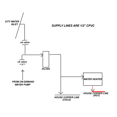
Air ConditionerOwner's ManualA Mermaid 12000 BTU air conditioner with reverse cycle heat, purchased June 2006 at a cost of 3478.25 is installed and provides cooling primarily to the aft cabin, although there are also two outlets in the main salon. The main salon outlets are located above and below the "electronics closet". The upper outlet is actually a dorade vent that has been converted to use as an air conditioner outlet. The aft cabin outlet is a fabricated "plenum box" below the hanging closet. The air conditioner is wired to the starboard outlet circuit breaker, through a 30-amp wall switch located inside the electronics closet. Sea water is used to cool the condensing unit. There is a ShurFlo strainer which uses a 50 mesh replacement screen available at Defender located in the bilge on the port side of the mast; this strainer needs to be checked from time to time and the screen should be replaced on a regular (annual) schedule. The thruhull that supplies the water is located just aft of the strainer. The (110VAC) water pump is located beneath the starboard settee. On occassion (especially after a wild ride or indeed after haulout), the pump needs to be "primed". To do this, loosen the (somewhat cumbersome) hose connection on the top of the pump and allow sea water to escape. The system is fitted with a Condensation Removal Device. Working on the "Venturi" principle, the Mermaid Condensator is installed in-line with the marine air conditioners' water discharge line. As the marine air conditioner and sea water pump are running, the device creates a vacuum effect and literally pulls the condensation water out of the drain pan and merges it with the discharge water. The condensator needs to be cleaned from time to time. It is located on the shelf underneath the air conditioner; there is an inline check valve within the plumbing line for the condensator. Fresh Water SystemFresh water is sourced from either a municipal connection through an inlet on the port side of the house, or from the house primary 115 gallon water tank, or from the 30 gallon bladder located within the starboard settee. 3/8" copper tubing that supplies all. Major "junctions" of the 3/8" copper tubing are found below the main cabin sole, just aft of the mast. Two opposing check valves fitted within the fresh water circuit provide seamless switching between a municipal water source and the on-demand house water pump (see diagram below). The check valves (SharkBite product U2008) have a cracking pressure of ½ PSI. To use the on-demand HOUSE water, eliminate municipal water supply pressure (disconnect the hose or shut off the faucet) and energize the on-demand pump using the 12vDC circuit breaker labeled FRESH WATER PUMP. There are no manual valves incorporated in the fresh water supply circuit. The higher pressure source automatically closes the opposing check valve, so if the on-demand pump is on and a higher pressure feed comes from the municipal source, water will be sourced from the municipal side. Conversely, if there's no municipal water pressure and the on-demand pump is on, water will be sourced from the house tank.
Reverse Osmosis FilterThe Reverse Osmosis water filtration system is located within the galley sink cupboard. A valve in the sink plumbing can shut off water supply to the reverse osmosis filtration system. Water HeaterAn IsoTemp
Slim 15 4 gallon (110v) water heater w/HX (2010) provides
sufficient hot water (if used sparingly). When the water heater
is turned on via the 110VAC circit breaker, a
red pilot light within the
electrical panel is illuminated. Aft head: Raritan PH2 with FreshHead upgrade. Pressurized water is sourced from sink cold supply line (angle stop). Currently (10/2022) direct discharge. ____________________________ Fwd head: MasterFlush Orbit electric. Pressurized water sourced from sink cold supply (angle stop). Plumbed to 23 gallon holding tank under forward berth although 3-way valve allows for direct discharge if necessary. Uses 50amp breaker marked HEAD. 20 amp fuse located inside sink base. Documentation is in the accessory binder. Three switches: 1: main flush (rocker) switch. When both secondary switches are illuminated the rocker switch will both fill and flush when activated. 2: (to the port side of the main switch) disables the inlet valve (water fill) and allows for dry flush. Illiminated indicates that the water fill valve is operational. 3: (to the starboard side of the main switch) disables the macerator pump and allows water to fill the bowl. Illuminated indicates that the macerator pump is operational. Pump out fitting is on the PORT side of the deck. Mostly ABS pipe and fittings throughout.
Galley (including propane) come back again---later |
|
|
.jpg)
.jpg)